In general, we define a synchronous sequential circuit, or just sequential circuit as a circuit with m inputs, n outputs, and a distinguished clock input. The description of the circuit is made with the help of a state table.
We have intentionally simplified our definition of sequential circuit. With our definition, the number of different states of the circuit is completely determined by the number of outputs. A more general definition separates the concept of output and the concept of state. Four our purposes, the additional generality is not needed, and we stall stick with our simple definition.
The same "goodness" criteria apply to the design of sequential circuits as to combinatorial circuits, i.e., number of transistors, speed, power consumption etc. Thus, as with combinatorial circuits, we are not going to discuss methods for obtaining optimal circuits, but only a very general method that in the worst case may waste a large number of tansistors. However, the purpose is not to turn the students into circuit designers, but to give them an idea of how sequential circuits work.
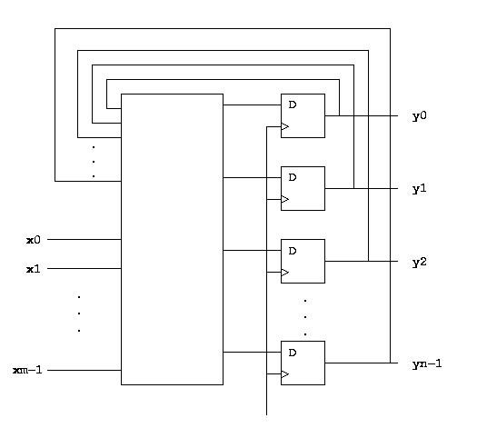
For a sequential circuit with m inputs and n outputs, our method uses n D-flip-flops (one for each output), and a combinatorial circuit with m + n inputs and n outputs. Here is the general structure of the resulting circuit:

Since we are using D-flip-flops, the outputs of the circuit after the next clock pulse is exactly the same as the output of the combinatorial circuit. We can therefore use our general method for building combinatorial circuits, this time applied to the state table of the sequential circuit.
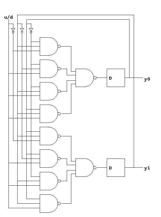
As an example, let us construct a 2-bit counter with an input indicating whether to count up or down (0 means down and 1 means up). The counter should stop at 00 when counting down and at 11 when counting up. Here is the state table for such a counter:
  u/d  y1 y0 | y1' y0'
  --------------------
   0   0  0  | 0   0
   0   0  1  | 0   0
   0   1  0  | 0   1
   0   1  1  | 1   0
   1   0  0  | 0   1
   1   0  1  | 1   0
   1   1  0  | 1   1
   1   1  1  | 1   1
With our general method, all we need to do is to build a sequential circuit from the truth table corresponding exactly to this state table. Here is the resulting circuit:
