However, there is a problem. It turns out that the normal way of creating such circuits would often use up way too many gates. We must search for different ways.
A full adder is a combinatorial circuit (or actually two combinatorial circuits) of three inputs and two outputs. Its function is to add two binary digits plus a carry from the previous position, and give a two-bit result, the normal output and the carry to the next position. Here is the truth table for a full adder:
   x y c-in | c-out s
   ------------------
   0 0  0   |    0  0
   0 0  1   |    0  1
   0 1  0   |    0  1
   0 1  1   |    1  0
   1 0  0   |    0  1
   1 0  1   |    1  0
   1 1  0   |    1  0
   1 1  1   |    1  1
Here, we have used variable names x and y for the inputs, c-in for the carry-in, s for the sum output and c-out for the carry-out.
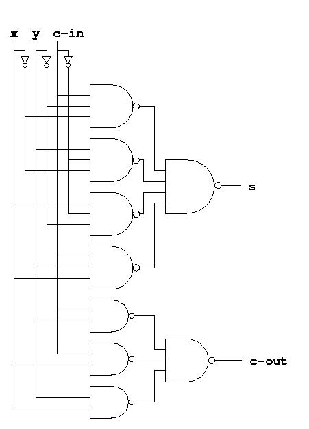
A full adder can be trivially built using our ordinary design methods
for combinatorial circuits. Here is the resulting circuit diagram:

The next step is to combine a series of such full adders into a circuit that can add (say) two 8-bit positive numbers. We do this by connecting the carry-out from one full adder to the carry-in of the full adder immediately to its left. The rightmost full adder takes a 0 on its carry-in.

Here, we have used subscript i for the i-th binary position.
As you can see, the depth of this circuit is no longer two, but considerably larger. In fact, the output and carry from position 7 is determined in part by the inputs of position 0. The signal must traverse all the full adders, with a corresponding delay as a result.
There are intermediate solutions between the two extreme ones we have seen so far (i.e. a combinatorial circuit for the entire (say) 32-bit adder, and an iterative combinatorial circuit whose elements are one-bit adders built as ordinary combinatorial circuits). We can for instance build an 8-bit adder as an ordinary two-level combinatorial circuit and build a 32-bit adder from four such 8-bit adders. An 8-bit adder can trivially be build from 65536 (216) and-gates, and a giant 65536-input or-gate.
Another intermediate solution consists of building so-called carry-accelerator circuits. [To be completed...]
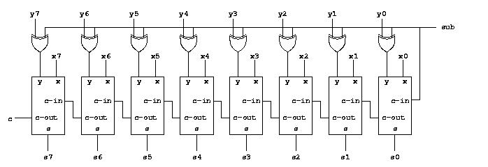
To see how this can be done, notice that in order to compute the expression x - y, we can compute the expression x + -y instead. We know from the section on binary arithmetic how to negate a number by inverting all the bits and adding 1. Thus, we can compute the expression as x + inv(y) + 1. It suffices to invert all the inputs of the second operand before they reach the adder, but how do we add the 1. That seems to require another adder just for that. Luckily, we have an unused carry-in signal to position 0 that we can use. Giving a 1 on this input in effect adds one to the result. The complete circuit with addition and subtraction looks like this:
